
Features of SecurePoE
The SecurePoE product family is designed to provide highly reliable PoE power for any network device, from a secure and practical package. Products are compliant with IEEE802.3:2012 (802.3at, 802.af) and designed for use with all compatible load devices. All versions feature secure plug-and-play connectivity with no software management. This allows deployment without programming and prevents remote interference with the power network.
- Secure tamper-monitored enclosures with all connections inside
- Mains and power status monitoring contacts
- Outdoor (IP66), 19" rack and indoor wall-mounting models available
- Guaranteed 30W per channel power to all outputs
- 90-270V AC, 47-63Hz universal mains input
- Ultra-high efficiency operation - up to 96%
- Designed for easy installation, set-up and maintenance
Monitoring
All models and variants of the SecurePoE range include single pole change-over (SPCO) relay monitoring contacts,
Individual PoE port status
Each PoE port has separate SPCO contacts and LED indicator for signalling the port status, such as:
- No device detected (LED off, SPCO NO)
- PoE device detected, connection in progress (LED flash, SPCO switching on/off)
- Device connected and using PoE power (LED on, SPCO NC)
SecurePoE power status
Every SecurePoE PCB module in the unit has an LED indicator to show that the PCB is powered. SPCO contacts allow remote signalling to other equipment in the event that PoE power can no longer be maintained.
Tamper monitoring
Indoor, exterior and rack-mount enclosures all include tamper monitoring. SPCO contacts change over from normally closed to normally open when the enclosure is opened. The tamper contacts also change over on rack-mount models if the remote battery pack is opened, or the cable is disconnected.
MidspanUPS & MultispanUPS also include monitoring of:
Power status
The power monitoring PCB module of MidspanUPS and MultispanUPS models and variants has an LED for visual indication and SPCO contacts for remote indication of mains power status. This is ideal for signalling via alarm panels or switching of other equipment in the event of a mains power failure. PoE power will be maintained during this state (as indicated by the separate SecurePoE power status LED and SPCO contacts on the SecurePoE PCB)
Battery low voltage
In the event of a prolonged mains power failure, the “Low volt“ contacts will change over to signal that the battery voltage is low and PoE power will shortly fail.
If mains power is not restored promptly and battery power is depleted to very low levels, then as a protection against deep-cycle damage, the battery pack will be disconnected. This will cause the power status contacts (on the PoE PCB) to change over and signal that PoE power can no longer be maintained.
Once mains power is restored, the battery pack will automatically be reconnected and re-charged, ready to maintain power again.
Power over Ethernet (PoE): what is power over Ethernet?
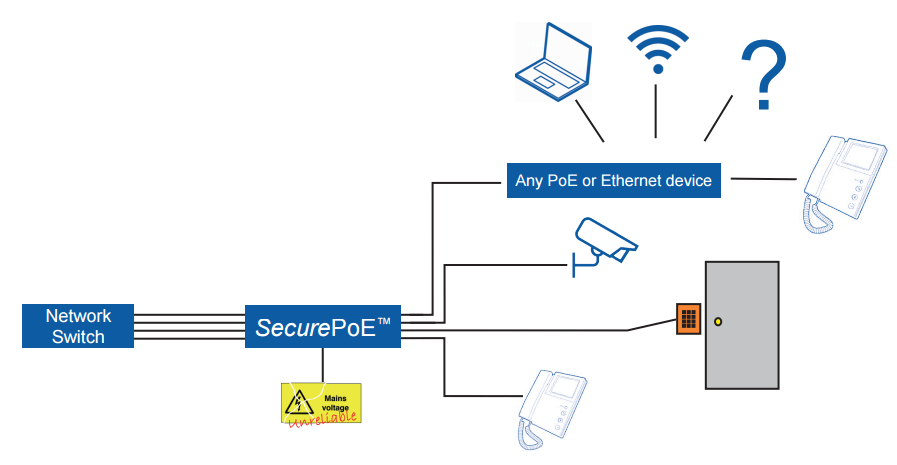
PoE offers an easy, fast and cost-effective solution for supplying power to products without the need to install power outlets and electrical cabling to the PoE devices. With the use of PoE, a network device can receive power over its Ethernet data transmission cable. PoE devices can therefore be installed in areas where traditional power cabling and outlets are unavailable, costly or difficult to install.
PoE has many applications, but the three key areas are:
VoIP phones: Power over Ethernet VoIP, the original PoE application. Using PoE means phones have a single connection to a wall socket.
IP cameras: Power over Ethernet cameras are now common on CCTV surveillance networks, enabling rapid deployment and easy repositioning.
Wireless: Wifi, Bluetooth and RFID readers are commonly PoE-compatible, to allow remote installation away from AC outlets and relocation following site surveys.
How does PoE work?
Network cables, such as Cat 5e and Cat 6, comprise eight wires arranged as four twisted pairs. In 10 and 100BASE-T Ethernet, two of these pairs are used for sending information, and these are known as the data pairs. The other two pairs are unused and are referred to as the spare pairs (Gigabit Ethernet uses all four pairs).
Because electrical currents flow in a loop, two conductors are required to deliver power over a cable. PoE treats each pair as a single conductor, and can use either the two data pairs or the two spare pairs to carry electrical current.
Power over Ethernet voltage
Power over Ethernet is injected into the cable at between 44 and 57 volts DC, and typically 48 volts is used. This relatively high voltage allows efficient power transfer along the cable while still being low enough to be regarded as safe.
This voltage is safe for users, but it can still damage equipment that has not been designed to receive PoE. Therefore, before a PoE switch or midspan (known as a PSE, for power sourcing equipment) can deliver power to a connected IP camera or other equipment (known as a PD, for powered device), it must perform a signature detection process.
Signature detection uses a lower voltage to detect a characteristic signature of IEEE-compatible powered devices (a 25kOhm resistance). Once this signature has been detected, the power sourcing equipment knows that higher voltages can be safely applied.
Classification
Classification follows the signature detection stage and is an optional process. If a powered device displays a classification signature, it lets the power sourcing equipment know how much power it requires to operate as one of three power classes. This means that power sourcing equipment with a limited total power budget can allocate it effectively. PoE power classes are as follows:
| Class | Current(mA) | Power range (Watt) | Class description |
|---|---|---|---|
| 0 | 0-4 | 0.44-12.94 | Classification unimplemented |
| 1 | 9-12 | 0.44-3.84 | Very low power |
| 2 | 17-20 | 3.84-6.49 | Low power |
| 3 | 26-30 | 6.49-12.95 | Mid power |
| 4 | 36-44 | 12.95-25.50 | High power |
The differences between power delivered by the power sourcing equipment and power received by the powered device account for power that is lost as heat in the cable. If a powered device does not display a signature, it is class 0 and must be allocated the maximum 12.95 watts.
Power over Ethernet plus (PoE+)
PoE Plus equipment has a power class of 4. If a regular 802.3af PoE source detects this class it will simply deliver power as if it were a class 0 device. However, 802.3at power sourcing equipment will not only recognise the powered device as a PoE Plus device, it will also repeat the classification stage as a signal to the powered device that it is connected to a power source with full PoE Plus power available. PoE Plus power sourcing equipment, such as SecurePoE, can supply up to 30 watts, and the available device power is 25.5 watts. SecurePoE also has no power budget and can supply 30 watts to all connected devices simultaneously.
The final stage after detection and classification of a newly connected device is to enable power: the 48V supply is connected to the cable by the power sourcing equipment so that the powered device can operate. Once power delivery is enabled, the power sourcing equipment continues to monitor how much electrical current it is delivering to the powered device, and it will cut the power to the cable if too much, or not enough, power is drawn. This protects the power sourcing equipment against overload and ensures that PoE is disconnected from the cable if the powered device is unplugged.
Where to buy
SecurePoE is available from all good stockists. A selection of some of the approved distributors is listed here.
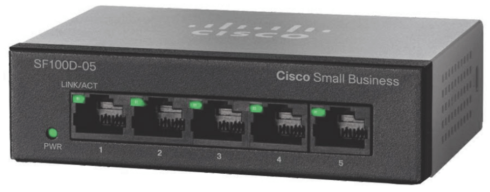
Multispan including integrated 5-port network switch
Multispan and MultispanUPS products include a 5-port network switch. They are available in indoor mild steel wall-mounting enclosures, exterior IP66 weather resistant enclosures ideal for harsh environments, or simply as 1U rack-mount products.
These switched Multispan models are ideal for installations where there is limited access to, or availability of, Ethernet ports on the network. Only a single Ethernet data cable is required to send and receive data from up to four devices that may or may not require power over Ethernet.
- Pre-installed within Multispan SecurePoE units
- No software to configure
- Network switch and PoE power are both battery backed with 1.2Ah, 7Ah and 10Ah MultispanUPS models
- Maintain data network during accidental or deliberate power failures or faults
- Gigabit Ethernet delivers high-speed connectivity to enhance network performance
- 200mm Ethernet cables to SecurePoE ports included
- Easily keep security infrastructure independent of existing networks
- Only one Ethernet cable is required to bridge to existing network infrastructure
- Ability to extend the range of power over Ethernet and network, up to 200m between network and PoE devices
MidspanUPS & MultispanUPS™
Designed for reliable battery back-up of PoE devices, our SecurePoE™ range includes battery-maintained MidspanUPS and MultispanUPS models that provide continuous power to PoE ports when mains power is not available. MultispanUPS models maintain power to the PoE ports and the integrated Cisco network switch.
Back-up power is provided by our replaceable, customised battery packs, which use high-reliability Yuasa batteries. Different capacities are available to cater for different standby time requirements and we offer guaranteed availability of replacement battery packs.
Whether powering CCTV cameras, video intercoms, locks or other device types, Power over Ethernet battery stand-by is available off-the-shelf.
Estimated stand-by times
| Output load | Battery capacity | ||
|---|---|---|---|
| 1.2Ah | 7Ah | 10Ah | |
| 5W | 9 Hours | 65 Hours | 100 Hours |
| 12W | 4 Hours | 30 Hours | 44 Hours |
| 25W | 1.75 Hours | 14.5 Hours | 20 Hours |
| 50W | 40 Minutes | 6.5 Hours | 9.5 Hours |
| 75W | 23 Minutes | 4 Hours | 6 Hours |
| 100W | 14 Minutes | 2.75 Hours | 4 Hours |